How to Choose a Proper Antenna for Your Use Case

When I started playing with SDRs, I mostly used whatever antenna came in the box. It had the correct connector, it was cheap, and it was already sitting on my desk. That was enough reason to plug it in. For local FM radio, nearby repeaters, or strong signals, it often worked well enough.
Then I started trying other things: ADS-B, satellite reception, amateur-radio bands, LoRa, random signals found during SDR sweeps, and remote signals that were not blasting through the front end. At that point, "whatever antenna came with the kit" stopped being a useful selection criterion.
The problem is not that generic antennas are always bad. The problem is that an antenna is part of an RF system. Its length, construction, frequency, feedpoint, mounting, nearby metal, cable, and radio all matter. An antenna that works reasonably well at 145 MHz may be a poor choice at 433 MHz, even if both frequencies appear in its online product description.
This post is about understanding that relationship well enough to choose an antenna deliberately. I will use my Bingfu eight-section BNC telescopic whip and a NanoVNA-H as a practical example.
DISCLAIMER: I'm not an SDR/RF expert, so this is just a representation of how I understand certain concepts. If at any point what I write seems wrong, that's probably it is and my understanding is incorrect or I explain it in a wrong way, in which case, feel free to correct it in the comments.
What an antenna actually does
An antenna converts electrical energy into electromagnetic waves when transmitting. When receiving, it does the reverse: an incoming electromagnetic wave produces a tiny electrical signal at the antenna connection.
A radio or transmitter sends an alternating electrical signal into the antenna. "Alternating" means the voltage and current repeatedly change direction. At radio frequencies, they change direction very quickly. That changing electrical energy creates changing electric and magnetic fields, which travel away as a radio wave.
A receiver or SDR works in reverse. The antenna interacts with an incoming wave, producing a small voltage that the receiver can amplify, digitise, and process.
Antenna choice depends primarily on your intended use and constraints. You first need to determine whether you are receiving or transmitting, as this directly affects design considerations. The exact frequency or frequency range is critical, since antennas are inherently frequency-dependent, and you must also decide whether broad coverage or optimal performance on a single band is more important. Practical factors come into play as well, such as whether the antenna needs to be portable or can be part of a fixed installation. Additionally, signal polarization (vertical or horizontal) must be matched for effective communication (briefly on that in a moment). Finally, consider physical and environmental limitations, including whether you can deploy a ground plane, radials, or a larger antenna structure.
Polarisation describes the orientation of a radio wave's electric field. A vertical whip normally receives and transmits vertical polarisation best. A horizontal dipole is normally horizontally polarised. A polarisation mismatch can reduce the received signal even when both antennas support the same frequency.
The visible metal is not the whole antenna
A telescopic whip is usually a monopole antenna. A monopole is one conductive element, typically a vertical metal whip, that works against a counterpoise. A counterpoise is the conductive part of the system that provides the RF return path.
Depending on the installation, the counterpoise can take many forms. It may be the metal chassis of a handheld radio, the shield of a coaxial cable, or a vehicle roof acting as a large conductive surface. In more controlled setups, it could be a dedicated metal plate or radial wires connected to the antenna ground. Measurement setups might even use the NanoVNA (more about this later) and adapter body as part of the counterpoise. In less ideal conditions, nearby conductive objects can unintentionally serve this role, and in some cases, unfortunately (or fortunately), even your own hand becomes part of the counterpoise. This is why connecting a whip straight to a NanoVNA, mounting it on a handheld radio, or attaching it to a long coax cable may produce different results.
The real antenna system is: whip + connector + feedline + counterpoise + mounting + environment.
A feedline is the cable between the radio and antenna. For RF work, this is often coaxial cable, usually shortened to coax. Coax has a centre conductor surrounded by insulation and an outer shield. The outer shield should normally provide the return path while helping prevent the cable from radiating or receiving unwanted signals.
In practice, the outside of a coax shield can become part of the antenna system. This is called common-mode current. It is one reason why cable routing can change a measurement.
Frequency and wavelength
A radio signal is characterized by its frequency, which represents the number of cycles it completes per second and is measured in hertz (Hz). For example, 1 kHz corresponds to 1,000 cycles per second, 1 MHz to 1,000,000 cycles per second, and 1 GHz to 1,000,000,000 cycles per second. In addition to frequency, radio waves have a wavelength, defined as the distance traveled during one complete cycle. These two properties are inversely related: lower frequencies correspond to longer wavelengths, while higher frequencies result in shorter wavelengths.
The fundamental formula is:
\[ \lambda = \frac{c}{f} \]
Here, \(\lambda\) is wavelength in metres, \(c\) is the speed of light, and \(f\) is frequency in hertz.
For practical work with MHz, use: \[ \lambda_{\mathrm{m}} \approx \frac{300}{f_{\mathrm{MHz}}} \]
At 100 MHz, the wavelength is roughly 3 metres. At 145 MHz, it is about 2.07 metres. At 433 MHz, it is about 69 cm. At 1090 MHz, the frequency used by ADS-B aircraft transponders, it is about 27.5 cm.
This matters because antenna dimensions are often fractions of a wavelength.
The quarter-wave starting point
A common vertical antenna is a quarter-wave monopole. A quarter-wave monopole is approximately one-quarter of the target wavelength long and uses a counterpoise or ground plane. A ground plane is a conductive surface used as the other half of the antenna system. A vehicle roof is a familiar example; a metal plate or several radial wires can be used on a bench.
The practical starting formula is:
\[ L_{\frac{1}{4}} \approx \frac{75}{f_{\mathrm{MHz}}}\text{ metres} \]
Some common examples:
| Target frequency | Approximate quarter-wave length |
|---|---|
| 20 MHz | 3.75 m |
| 50 MHz | 1.50 m |
| 100 MHz | 75 cm |
| 145 MHz | 51.7 cm |
| 433 MHz | 17.3 cm |
| 868 MHz | 8.6 cm |
| 1090 MHz | 6.9 cm |
If I want to receive or transmit primarily near 145 MHz, a whip around 52 cm is a useful place to start. For 433 MHz, a quarter-wave is much shorter: around 17 cm.
This is not a final cut list. It is a first approximation.
Real antennas are affected by their diameter, taper, base construction, connector, insulation, counterpoise, nearby materials, and mounting position. They are often slightly shorter than the formula suggests because the electrical field extends beyond the physical end of the conductor. This is called an end effect.
The formula gets you into the right neighbourhood. Measurement gets you to the correct address.
What does it mean to be resonant?
An antenna is resonant at a specific frequency when its electrical behaviour is balanced at that frequency. More precisely, resonance occurs when the antenna's net reactance is close to zero. Reactance is one part of impedance. Impedance is the total opposition an antenna presents to an alternating signal. It is measured in ohms. Impedance is normally written as: \[ Z = R + jX \] Where:
- \(Z\) is total impedance.
- \(R\) is resistance.
- \(X\) is reactance.
- \(j\) is the engineering notation for the reactive component.
Resistance is the part associated with energy transfer and loss. In an antenna, measured resistance can include energy radiated as RF as well as losses in wiring, connectors, matching components, or nearby materials.
Reactance describes energy that is temporarily stored and released by electric and magnetic fields rather than dissipated as heat. Negative reactance indicates capacitive behavior, while positive reactance indicates inductive behavior. When reactance is zero, the capacitive and inductive effects cancel each other out.
At resonance: \[ X \approx 0 \] The antenna's impedance becomes mostly resistive: \[ Z = R + j0 \]
For a simple whip, negative reactance often means it is electrically short at the tested frequency. Positive reactance often means it is electrically long. This is a helpful rule of thumb, although real antennas can behave less cleanly because the antenna base, counterpoise, feedline, and surroundings all contribute.
The useful practical rule is that making a whip antenna longer normally shifts its main resonance to a lower frequency, while making it shorter shifts the resonance to a higher frequency. A telescopic whip is particularly convenient because it lets you test and observe this relationship directly by changing its length.
Resonance is not the entire answer
Resonance alone does not mean that an antenna is a good match for your radio. Most RF equipment is built around a 50-ohm system. That includes transceivers, SDRs, RF test equipment, many filters, and common RF coaxial cables.
The ideal antenna feedpoint impedance for a 50-ohm system is: \[ Z = 50 + j0\Omega \]
This means the antenna presents approximately 50 Ω of resistance with close to zero reactance, providing a reasonable electrical match to the connected radio and coaxial cable.
But these examples are both resonant: \[ Z = 8 + j0\Omega \]
\[ Z = 500 + j0\Omega \] Both have zero reactance. Neither is close to 50 ohms.
An antenna with either value may need a matching network. A matching network is a circuit using capacitors, inductors, or transformers to make the antenna impedance appear closer to the impedance expected by the radio.
The result we want is therefore not merely "resonant." We want resonance and a reasonable 50-ohm match in the same area: \[ Z \approx 50 + j0\Omega \]
What mismatch means
When a 50-ohm transmitter connects to a 50-ohm cable and a 50-ohm antenna system, RF energy transfers with little reflection. If the antenna impedance differs substantially, part of the transmitted signal is reflected back along the feedline instead of being accepted by the antenna system. For a transmitter, excessive reflected power can reduce the power reaching the antenna and may cause the radio to reduce output power or activate protection circuitry. For an SDR or receiver, mismatch normally does not cause damage. It can still affect the amount of signal reaching the receiver and its response across frequency. This is why an antenna listed as "20–1300 MHz" should not automatically be treated as a well-matched transmitting antenna over that entire range.
The NanoVNA as a reality check
A NanoVNA is a small vector network analyzer, or VNA.
For antenna work, it sends a low-power RF test signal into the antenna and measures how much returns. It does not measure real on-air signal strength, gain, efficiency, or radiation pattern. It measures electrical behaviour at the feedpoint.
The main measurement is called S11. S11 means "reflection seen at port 1." On the NanoVNA-H, port 1 is CH0. A low reflected signal suggests that the antenna system is reasonably close to the 50-ohm reference impedance. A high reflected signal means it is poorly matched.
The NanoVNA can display the same information in several ways:
- S11 or return loss
- SWR
- Resistance
- Reactance
- Impedance
- Smith chart
For this experiment, it answers two questions:
- Is the antenna near resonance at my target frequency?
- Is it a reasonable match for 50-ohm equipment at that frequency?
NanoVNA antenna tests use CH0 for reflection measurements; calibration is performed after selecting the desired frequency range, using open, short, and 50-ohm-load standards.amris.mbi.ufl+1
Reading SWR and return loss
Return loss expresses the reflected signal in decibels, dB. More-negative values mean less reflection. SWR means standing-wave ratio, and it is another way to express the same mismatch.
A standing wave appears when forward RF energy and reflected RF energy coexist on a cable. SWR expresses how strong that effect is.
Useful approximate values:
| Return loss | SWR | Reflected power | Meaning |
|---|---|---|---|
| -3 dB | 5.85:1 | 50% | Very poor match |
| -6 dB | 3:1 | 25% | Poor match |
| -9.5 dB | 2:1 | 11% | Usually acceptable |
| -14 dB | 1.5:1 | 4% | Good match |
| -20 dB | 1.22:1 | 1% | Very good match |
A 2:1 SWR result means that, at one specific frequency and with one specific physical arrangement, roughly 11% of power is reflected and about 89% is accepted by the antenna system. That can be a perfectly good practical result. It does not prove that the antenna has high gain, high efficiency, a useful radiation pattern, or strong receive performance. A dummy load is the classic example: it can present an almost perfect 50-ohm match and show excellent SWR while turning RF energy into heat instead of radiating it.
My example antenna
The antenna I want to test is a Bingfu BNC telescopic whip with eight sections. The vendor lists it as 26–122 cm long, for 20–1300 MHz, with 50-ohm impedance and VSWR below 2:1. Those are product claims; the point of testing is to see what happens in a specific setup.
The length gives us an immediate clue. At full extension, 122 cm is far shorter than the 3.75 m quarter-wave required at 20 MHz. The whip may receive something at 20 MHz, but I should not expect a naturally resonant, full-size quarter-wave behaviour there.
At VHF, a fully extended 122 cm whip is closer to useful electrical lengths. It may have resonances elsewhere too, particularly at higher frequencies, but the actual result depends on the counterpoise and installation.
Test setup
For the basic test, I need:
- NanoVNA-H
- Bingfu BNC telescopic whip
- A short SMA-to-BNC-female adapter
- Open, short, and 50-ohm load calibration standards
- A stable, non-metallic support
- Optionally, a metal plate or radial wires for a deliberate counterpoise
The NanoVNA-H uses SMA connectors. The Bingfu has a BNC plug. You'd prefer a short solid adapter instead of a long pigtail, because a cable can become a meaningful part of the RF system. Still, I'm gonna use my test bench with a cable, and account for that during the calibration.
If you use a metal plate or radial wires attached to the connector ground, you create a more deliberate counterpoise. This lets you compare a random bench setup against something closer to a controlled monopole installation.
Calibrating the NanoVNA
Calibration is not optional. It tells the NanoVNA where the measurement should begin. This location is called the reference plane.
Ideally, I want the reference plane at the BNC connection where the whip plugs in, but again, I'm using my test bench with NanoVNA extension cable. That means the VNA measures the antenna system rather than the antenna plus unknown adapter behaviour.
For a one-port antenna measurement, I perform OSL calibration:
- Select the frequency range to be tested.
- Attach the open standard and select Open.
- Attach the short standard and select Short.
- Attach the 50-ohm load and select Load.
- Finish and save the calibration.
- Reconnect the load and confirm it reads close to 50 ohms and 1:1 SWR.
If I calibrate directly on the NanoVNA with SMA standards and then install the BNC adapter, the adapter remains part of the measurement. That is still useful for exploratory testing, but calibration at the actual antenna connection is better.
The calibration must be repeated whenever I substantially change the frequency span, adapter/cable arrangement, or intended reference plane.
Running the test
You could begin with a single 20–1300 MHz sweep and call it done. A broad sweep can find rough features, but a narrow sweep gives a better view of the minimum SWR, the reactance crossing, and the usable range around a target frequency.
So, that's what I would use broad sweeps first:
- 20–100 MHz
- 100–250 MHz
- 250–550 MHz
- 550–900 MHz
- 900–1300 MHz
Then I will narrow in around anything interesting.
For example:
- A possible VHF dip near 145 MHz: sweep 130–160 MHz.
- A possible UHF dip near 433 MHz: sweep 400–470 MHz.
- A possible 868 MHz dip: sweep 820–920 MHz.
- A possible ADS-B-region dip: sweep 1000–1200 MHz.
For each narrow sweep, I would enable:
- SWR
- Return loss or S11 LogMag
- Resistance and reactance, or a Smith chart
S11 LogMag means the magnitude of S11 shown on a logarithmic dB scale. It makes reflection dips easy to see.
A Smith chart is a circular graph showing impedance. Its centre is the 50-ohm, zero-reactance point. A trace close to the centre is a good match. The upper half represents inductive reactance; the lower half represents capacitive reactance.
What I am looking for
A useful frequency is not just the deepest line on the screen. I look for several things happening together:
- A local minimum in SWR
- A dip in return loss
- Reactance close to zero
- Resistance in the neighbourhood of 50 ohms
- A Smith-chart trace that approaches the centre
- A result that remains similar when I reconnect the antenna
If the best SWR point is at a lower frequency than I want, the whip is usually electrically too long, and I can shorten it. If the best point is above my target, the whip is usually too short, and I can extend it. This assumes a simple whip-like antenna and a stable counterpoise; it is not a universal rule for every commercial antenna design.
Testing the telescope check the actual values
The real experiment is to repeat the measurement at different lengths:
- Fully collapsed
- About one-quarter extended
- Half extended
- Three-quarters extended
- Fully extended
For each length, I would write down:
- Physical whip length
- Counterpoise arrangement
- Frequency of lowest SWR
- Minimum SWR
- Frequency where reactance is nearest to zero
- Resistance and reactance at that point
- The frequency range where SWR remains below 2:1
Actual testing and results
For the purpose of this blog post, I've done a test on a 20-100MHz range with a fully extended antenna. The antenna was screwed on a test bench, connected via cable to the NanoNVA-H (working as the counterpoise):
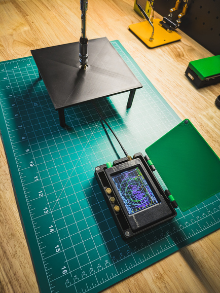
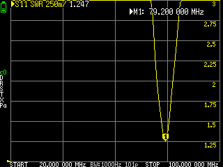
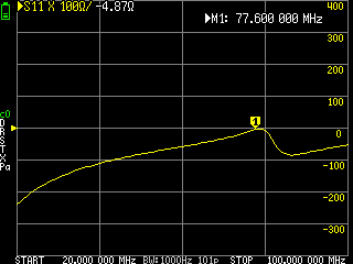
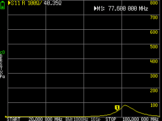
Note: as you probably noticed, some of the values on the screenshots are different from the ones I reported above. That's because the moment I touched the NanoVNA, the values change, in some cases significantly - this is how the external factors can affect your antenna system!
With this I can say that the whip fully extended and the cable plus NanoVNA acting as the counterpoise, my antenna system has:
| Parameter | Result |
|---|---|
| Lowest SWR | ~1.2:1 at 80 MHz |
| Near-resonant point | 77.6 MHz |
| Impedance at 77.6 MHz | \(35 - j12\Omega\) |
| SWR below 2:1 | Approximately 70–80 MHz |
My system is therefore near resonance around 77.6 MHz and has its best 50-ohm match very close by, at approximately 80 MHz. This is exactly the kind of relationship you would hope to see: the resonance point and minimum-SWR point are close but not identical. NanoVNA antenna measurements commonly use the zero-reactance point to identify resonance and the SWR minimum to identify the best match to 50 ohms.
What \(35 - j12\Omega\) means
At 77.6 MHz, the measured impedance is: \[ Z = 35 - j12\Omega \] This means:
- 35 ohms resistance: Lower than the 50-ohm target, but not dramatically so.
- -12 ohms reactance: Capacitive; the antenna system is still slightly electrically short at 77.6 MHz.
- Near resonance: -12 ohms is not zero, so this is not exact resonance, but it is much closer to resonance than the original 20 MHz reading.
The impedance magnitude is: \[ |Z| = \sqrt{35^2 + (-12)^2} \approx 37\Omega \]
This confirms that this marker is a plausible near-resonant point. It is not yet a perfect 50-ohm match, but it is in the right neighbourhood.
If I could find a frequency slightly above 77.6 MHz where $X$ reaches 0 ohms, that is the actual resonant frequency. Given my 80 MHz SWR minimum, it is plausible that the zero-reactance crossing is somewhere around 78–80 MHz; I could use a narrow sweep to locate it precisely.
What the 80 MHz SWR dip means
An SWR of approximately 1.2:1 is excellent from a matching perspective. It corresponds to only about 0.8% reflected power, so about 99.2% of forward power is accepted by the antenna system at that frequency.
A careful conclusion is:
With the Bingfu whip fully extended, and with the NanoVNA plus cable acting as its counterpoise, the antenna system is close to resonance around 77.6 MHz and has an excellent 50-ohm match near 80 MHz. Its measured SWR stays below 2:1 from approximately 70 MHz to 80 MHz.
This is a statement about that specific system, not the whip by itself. Change the cable length, move the NanoVNA, attach the antenna to a handheld radio, or add a metal ground plane, and the result may shift.
The 70–80 MHz bandwidth
My below-2:1 SWR range is about 10 MHz wide. That is a useful matched bandwidth in relative terms: \[ \frac{80 - 70}{77.6} \times 100 \approx 12.9\% \] A roughly 13% fractional bandwidth is fairly broad for a simple compact whip setup. It may indicate that the system is being influenced by the cable and NanoVNA counterpoise, or that loss in the overall setup is broadening the match. That is not automatically bad, but it is a reason to repeat the test with a deliberate and repeatable counterpoise before drawing conclusions about the whip alone. Remember: I only tested the fully extended antenna at the 20-100MHz frequency range!
Validate it on air
The NanoVNA tells me whether the antenna is resonant and matched. It does not tell me whether it receives weak signals well or radiates efficiently. For that, I need an on-air comparison. I can compare the telescopic whip to a known reference antenna while receiving ADS-B traffic, a weather-satellite pass, or whatever else it might be. I'd then keep the receiver, SDR gain, cable, location, antenna orientation, and time window the same. Then I compare signal strength and signal-to-noise ratio. Signal-to-noise ratio, or SNR, compares the wanted signal with the background noise. It is often more useful than raw signal strength because a stronger signal is not always better if the noise rises by the same amount.
The major issue with on-air testing is that, well, you need to have a system that you know it behaves in an expected way, which you could use as a reference. I don't have one so, no on-air testing for me.
Choose deliberately
The correct antenna depends on the use case. For a narrow target frequency, such as 145 MHz or 433 MHz, a correctly sized quarter-wave whip, dipole, or purpose-built antenna is usually more predictable than a broad "20–1300 MHz" telescopic antenna. For general SDR scanning, portability may matter more than perfect matching, so a telescopic whip can be a good compromise. The important change is not buying the most expensive antenna. It is moving from "this came with the kit" to a clear question: "What signal do I care about, at which frequency, in what physical installation, and is this antenna system actually resonant and reasonably matched there?"
Conclusions
Choosing an antenna is not about finding one with the correct connector or the broadest frequency range printed on the package. It starts with identifying the signal or band you care about, whether you are receiving or transmitting, and the physical constraints of the installation.
An antenna works in relation to wavelength. A useful starting point for a basic quarter-wave whip is: \[ L_{\frac{1}{4}} \approx \frac{75}{f_{\mathrm{MHz}}}\text{ metres} \] This gives an approximate physical length, not a final design. The real resonant frequency also depends on the antenna base, whip diameter, counterpoise, cable, mounting, and nearby objects.
Resonance means that the antenna's reactance is near zero. In practical terms, it is not behaving mainly like an electrically too-short or too-long reactive element at that frequency. Extending a telescopic whip usually moves its main resonance lower in frequency; shortening it usually moves it higher.
Resonance alone is not enough. A resonant antenna may still have a resistance far from the 50-ohm impedance expected by typical radios, SDRs, coax, and test equipment. The most useful result is therefore: \[ Z \approx 50 + j0\ \Omega \] This means the antenna is near resonance and is also reasonably matched to a 50-ohm system.
The NanoVNA-H helps verify this rather than relying on antenna marketing claims. It measures reflected signal at the feedpoint and displays it as S11, return loss, SWR, resistance, reactance, and impedance. For a practical measurement, look for low SWR, return loss better than roughly -10 dB, resistance reasonably close to 50 ohms, and reactance close to zero.
An SWR of 2:1 is often acceptable, especially for portable equipment. It means that roughly 11% of the forward power is reflected and roughly 89% is accepted by the antenna system. It does not prove that the antenna has good gain, efficiency, radiation pattern, or receive performance.
Finally, the whip is only part of the antenna. Its counterpoise (such as the radio chassis, coax shield, metal plate, radial wires, or nearby conductive objects) can move resonance and change SWR significantly. Test the antenna in the same configuration in which you intend to use it, then validate the NanoVNA result with a real on-air comparison against a known reference antenna.
When I started getting into SDR, most of the times I tried to do something, things just didn't work as I expected. Because of that I kept asking myself: where the problem is? Is it the receiver, is it the software I developed, or is it the antenna? In many cases I can confirm that the received works as expected by tunning it to a known FM and see if I pick up something meaningful. The software I can debug and test with GNU Radio. But the antennas, it's almost like a black magic, which I spent most of the last weekend trying to figure out, and I still can't say I feel like I grasp the basics. That said, I feel I know a little bit more now and that gives me confidence and encourages me to keep playing with SDR, and start making more deliberate choices when it comes to choosing the right tools for the job. I hope this article will help you too.
Resources
Here is a list of resources I made use of while learning and writing this article.
Antenna fundamentals
Practical Antennas, "The Importance – or Not – of Antenna Resonance." Useful context on resonance, feedpoint reactance, and why resonance alone is not a complete measure of antenna performance.
Dino Bell, "Antenna Resonance." Explains standing waves, quarter-wave elements, and resonant lengths including odd quarter-wave multiples.
Ham Radio School, "A Simple View of Resonance." A readable explanation of why antenna length affects resonant frequency and why longer antennas resonate at lower frequencies.
Ham Stack Exchange, "What exactly makes an antenna resonant?" Technical discussion of resonance as zero feedpoint reactance and the relationship between antenna inductance and capacitance.
Wikipedia, "Monopole antenna." General reference on monopoles, ground planes, and the relationship between a monopole and a dipole.
NanoVNA and antenna measurements
NanoVNA, "Start measurement." Official-style workflow: set the frequency range, calibrate the instrument, connect the device under test, and select display traces.
NanoVNA User Guide, "NanoVNA User Guide." Covers calibration, S11, impedance, Smith charts, and antenna measurements with the original NanoVNA.
NanoRFE, "Antenna SWR Tuning | NanoVNA." Practical guide to measuring SWR, identifying resonance, and tuning antennas with a NanoVNA.
KARS, "Tuning and Testing Antennas with the NanoVNA: A Starter's Guide." Beginner-oriented instructions for OSL calibration, CH0 antenna measurements, SWR traces, and basic interpretation.
Nodak Mesh, "NanoVNA Antenna Testing for 915 MHz LoRa Mesh Nodes."
Practical example of using NanoVNA for a real target band, including calibration, impedance, SWR, and measurement caveats.
Astronomy.me.uk, "A Simple Way to Test an Antenna with a NanoVNA." Concise practical sequence for connecting, calibrating, sweeping, and interpreting SWR measurements.
Product details
Bingfu, "20–1300 MHz 8 Sections Telescopic BNC Male Antenna."
Product listing referenced for the vendor-stated 20–1300 MHz range, 26–122 cm physical length, eight-section design, BNC connector, 50-ohm impedance, and VSWR claim.